AC
01Overview 02About 03Technical 04Process 05Gallery 06Results
← BACK TO PORTFOLIO
IEEE ROBOTICS

IEEE
Robotics.

Designed and built the peripherals control system for a competition robot, integrating servos, time-of-flight sensors, a magnetometer, a light sensor, PID-based analog servo control, and UART communication around an STM32 microcontroller. From early architecture planning through soldered protoboard to a working, competition-ready control system.

ROLE: Peripherals Design
DATE: Aug 2025 — Current
TYPE: Hardware
STATUS: Renewed
FIG. 01 — PROJECT OVERVIEW
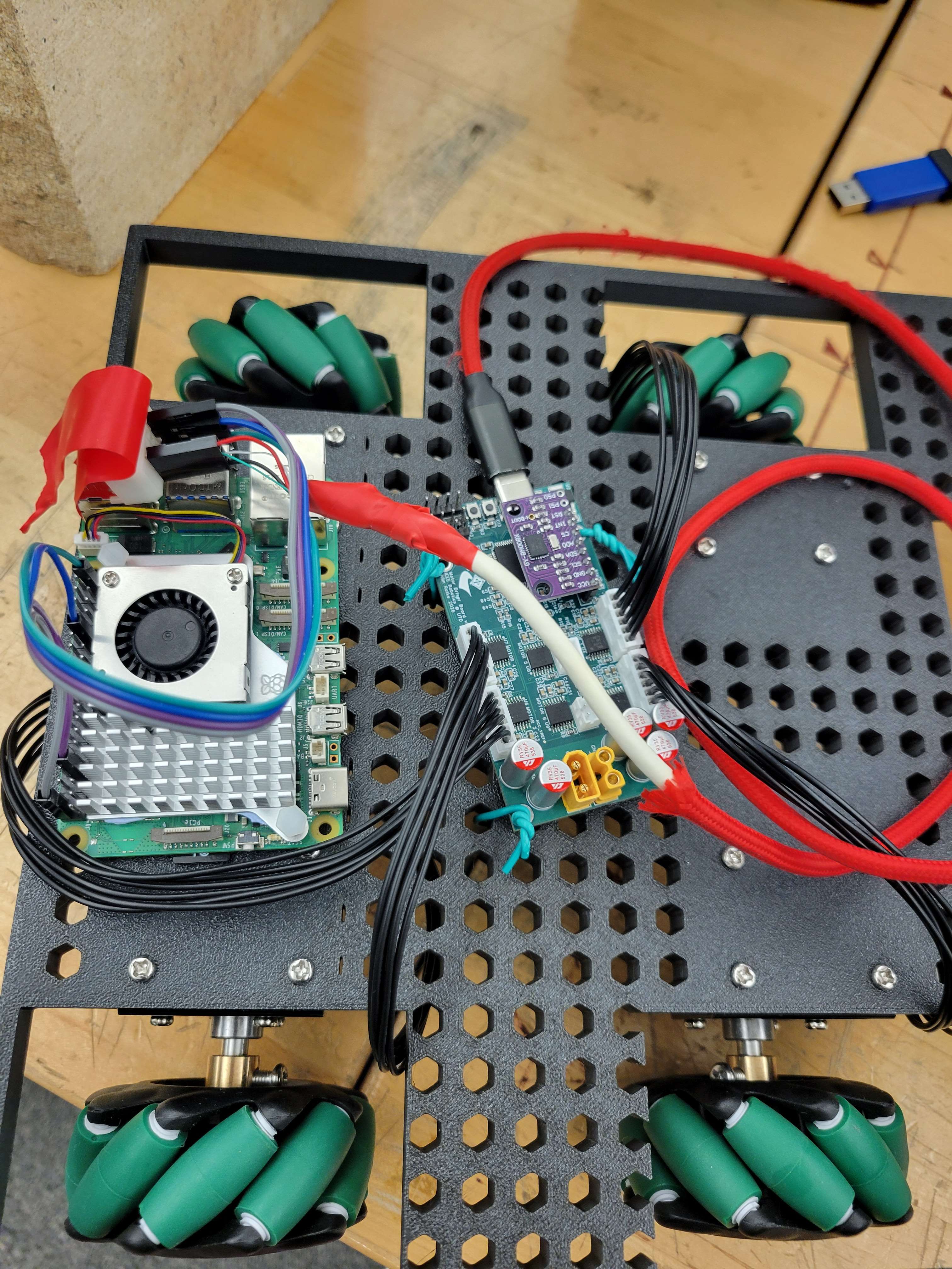
IEEE Robotics competition robot
About the Project

What I Built

Problem

This year's competition robot needed to do more than just drive from point A to point B. It had to physically move two containers across the playing field, place a beacon at a marked location, tell two different types of icosahedron elements apart, sort them, and release each one into the correct container, all without any manual intervention once the run started.

To make that possible, the team split into three subteams: software, hardware, and electrical. My focus was on the electrical side, where the core problem was building a circuit-board system that could reliably control both the robot's drivetrain and every peripheral device riding on top of it — servos, distance sensors, a magnetometer, and a light sensor, without any single component's wiring or timing interfering with another's.

Solution

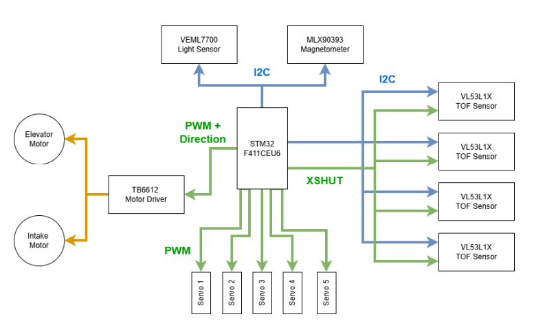
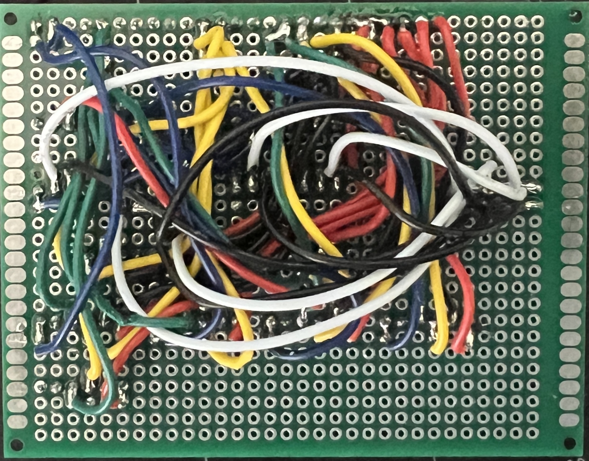
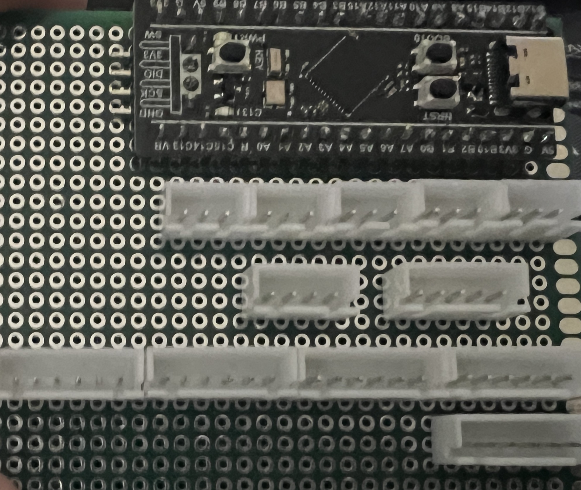
My first responsibility was planning the overall peripherals architecture. This included deciding which sensors and actuators the robot actually needed, how they'd be wired, and how the STM32 would talk to each of them without conflicts on shared communication lines. As competition priorities shifted and the timeline tightened, I moved from architecture into hands-on execution: designing, wiring, and soldering a protoboard that gave every sensor and servo a dedicated connection point back to the team's chosen STM32 microcontroller.

Rather than treating that board as a one-off fix, I built it to be debuggable. I made it clearly labeled headers, isolated power runs for the higher-draw servos, and enough slack in the layout that a single failing sensor could be swapped without re-wiring the whole board. That decision paid off repeatedly during testing, when individual components needed to be pulled and replaced without taking the rest of the system down.
Technical Specifications

System Architecture

Microcontroller STM32 microcontroller board
Programming Embedded C
Hardware Standard servos, analog servos, time-of-flight sensors, magnetometer, light sensor, protoboard
Communication I²C, UART
Software STM32CubeIDE
Key Concepts PID servo control, sensor integration, localization sensing, peripheral control, multicomponent hardware integration
Architecture

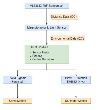
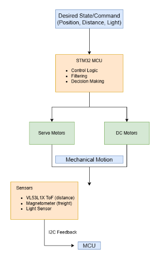
System Diagram

FIG. 02 — SYSTEM ARCHITECTURE
IEEE Robotics peripherals system block diagram
Electrical Design

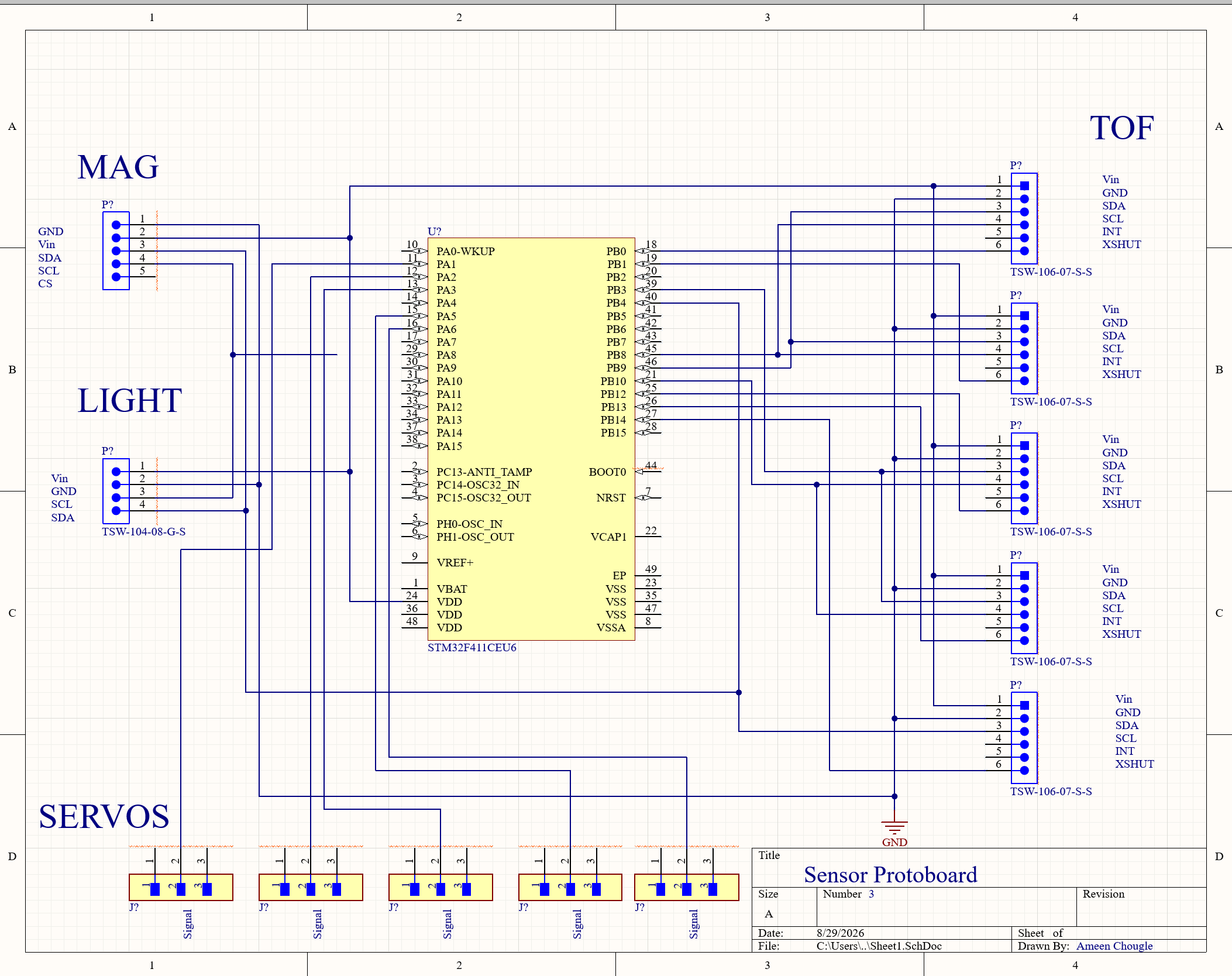
Peripheral Schematic

FIG. 03 — PERIPHERAL SCHEMATIC
IEEE Robotics peripheral schematic
Development Process

How It Was Built

01

Design

The robot needed to move two containers across the field, place a beacon, sort two types of icosahedron elements, and release them into their respective containers. The design also required sensors for localization, distinguishing magnetic from non-magnetic elements, and detecting the start light that initiated the robot's tasks. Every one of these requirements had to be mapped to a specific sensor or actuator before a single wire was cut, so the earliest design work was really about turning a competition rulebook into a concrete parts list and wiring plan.

02

Implementation

Standard servos were selected for container movement, beacon placement, sorting, and element release because they provided precise motion in a compact form. Time-of-flight sensors handled localization, a magnetometer distinguished element types, and a standard light sensor detected the start condition. Each of these went through the protoboard, so getting the pin mapping and firmware drivers right for every device — before trying to run them together — was a big part of making this stage go smoothly.

03

Testing

Testing revealed three major issues: servos in the icosahedron transfer path could become stuck, the original time-of-flight sensor orientation created a localization blind spot, and the IMU on the driver-side board interfered with the magnetometer and produced faulty readings. None of these showed up in isolated bench tests — they only surfaced once the full system was running together under real competition conditions, which made structured, repeatable test runs essential.

04

Optimization

Certain standard servos were replaced with analog servos and controlled using a PID algorithm so they could correct their position when elements became stuck. A corner-mounted time-of-flight sensor orientation removed the localization blind spot, and the magnetometer was moved off-board to reduce interference from the nearby IMU. Each fix targeted the root cause identified in testing rather than papering over the symptom, which kept the same failure from reappearing later in a different form.

05

Integration

The original concept was a custom PCB with dedicated peripheral ports and the STM32 integrated directly into the board. Resource constraints and timeline changes led to replacing that design with a protoboard that preserved the required peripheral connections while reducing build time. That pivot meant re-checking every net from the original schematic by hand to make sure nothing was lost in translation between the two layouts.

06

Final Build

The final protoboard included dedicated ports for the separate devices and a connection for the selected STM32 board. Firmware incorporated the PID-based servo changes and updated time-of-flight logic to control the sensors and servos, while serial UART communication linked the driver board and peripherals board into a complete robot control system. The result was a board the team could trust to run full competition sequences end to end, not just isolated demos.

Results

Outcomes

Challenges

  • One of the main challenges was preventing servos from getting caught on the icosahedron elements mid-transfer, which would stall the entire sorting sequence.
  • Multiple approaches were considered, including changing the intake structure and adding physical protection around the moving servo arm, before settling on a control-side fix.
  • Switching to analog servos and enabling PID-based movement provided more precise control and a more effective, self-correcting solution than any purely mechanical fix.
  • Sensor interference between the magnetometer and the driver board's IMU was subtle enough that it took several rounds of isolated testing to trace back to its actual source.

Lessons Learned

  • Plan ahead and expect major design changes; the switch from a PCB to a protoboard required a complete redesign of the original plan, not just a substitution of parts.
  • I learned a lot about multicomponent integration, communication protocols, and the practical, real-world quirks of different sensor types that datasheets don't always mention.
  • Debugging a system built from several independently-sourced components taught me to isolate variables early — testing one sensor or servo at a time before trusting the full system.
  • In a future version, I would prefer a final custom PCB rather than a protoboard for a cleaner, more reliable, and more finished implementation.